

After a long time of doing mostly virtual (software) stuff, I felt it was time for another hardware project. I’ve always been fascinated by the old Nixie tubes, and had ordered a bunch of them before they get too expensive or become impossible to find. The obvious thing to use them for is a clock. I wanted to go for a mix of old (the Nixies) and new, so the clock is driven by a Raspberry Pi – meaning it will have WiFi and NTP so I never need to update it to the correct time even on daylight savings changes.
There are many Nixie driver circuits online, finally I settled for an option from this page which uses a single K155ID1 as the kathode driver and anode multiplexing using optocouplers, mainly to reduce component count. The TLP627 optocoupler works nicely, but takes a while to turn off – leading to “bleeding” of one tube’s value into the next one unless long blank periods are introduced. However too long blanking times will severely reduce maximum brightness when combined with 4-way multiplexing so the display becomes hard to read in bright sunlight. Another site added 330kΩ resistors between the TLP’s output and ground, I didn’t have these initially but adding them helped to remove the charge left on the TLP’s output transistor meaning the Nixie turns off much faster. Now with 600µs of blanking time there is no visible bleeding even at maximum brightness. A pair of IN-3 (labeled INS-1 in the schematic) form the colon dots between HH and MM, and are driven by a discrete MPSA42 high-voltage transistor.
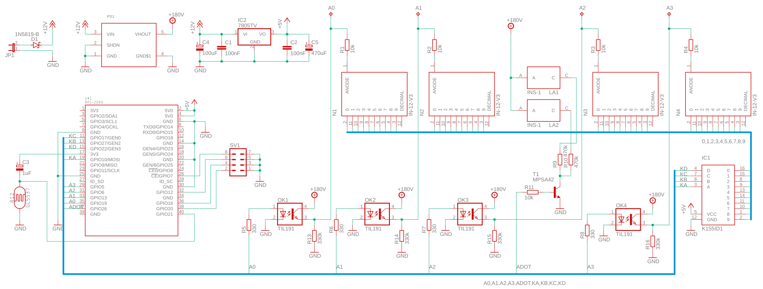
The clock is powered by a regular 9V power brick. A NCH6100HV high voltage module boosts this up to +180V to drive the Nixie anodes, while a 7805 generates +5V for the Raspberry Pi. When the Pi is very active it draws quite a bit of power, so C4 and C5 were needed to stabilize the 5V. Recompiling the kernel module on the Pi proved a good test for the power delivery. Also since the 7805 is a simple linear regulator it becomes quite hot – the NCH6100HV officially needs 12V but then the dissipation of the 7805 was just too much. So instead I went for a 9V supply voltage, this seems to work well enough for the NCH6100HV module. A better solution would use a switching power supply for the Pi, at the cost of extra complexity.
To allow the clock to adapt its brightness to the ambient lighting conditions, I added a light sensor inspired by this page. Since the Raspberry Pi has no analog inputs, an RC network is created using R12, a GL5537 LDR, and C3. Setting GPIO21 as an output and making it high will discharge the capacitor, then GPIO21 is set as an input and the time is measured until it becomes low. With 1µF and the LDR’s nominal resistance of 37kΩ the RC time constant is 37ms, measured times range from 10ms in bright sunlight to about 50-100ms in near darkness.
Schematic and a PCB were drawn up in Eagle. I made it fit in just under 100mm to stay inside the limits of the free version. PCBWay is a great place to get PCBs for these types of projects, $10 got me 10 two-layer PCBs with metallization and silk-screening. I could even choose a black finish which looks really nice.

Software on the Raspberry Pi Zero W consists of a kernel module that multiplexes the IN-12 nixie tubes, turns the IN-3 colon dots on and off, and reads the light sensor, all through a single hrtimer callback while communicating with userspace through a set of sysfs files. A Python program specifies the values on the display by writing to /sys/nixie/value, it also reads the light sensor through /sys/nixie/light to get a value in milliseconds. It then uses a conversion table to determine the duty cycle for the Nixies. In addition, the kernel module contains an extra set of multipliers to tweak the intensities per display and per digit. The former is needed because the quality of my Nixie tubes isn’t uniform, the latter equalizes the apparent intensity of the different digits because of their size and position in the stack. E.g. the “3” is mounted at the front and appears much brighter, while the “2” is at the very back and gets obscured by all other digits so I run it about 4x longer to make both appear to have roughly the same intensity. At full intensity this isn’t much of a problem, but at low ambient light the effect with equalization is a lot nicer.
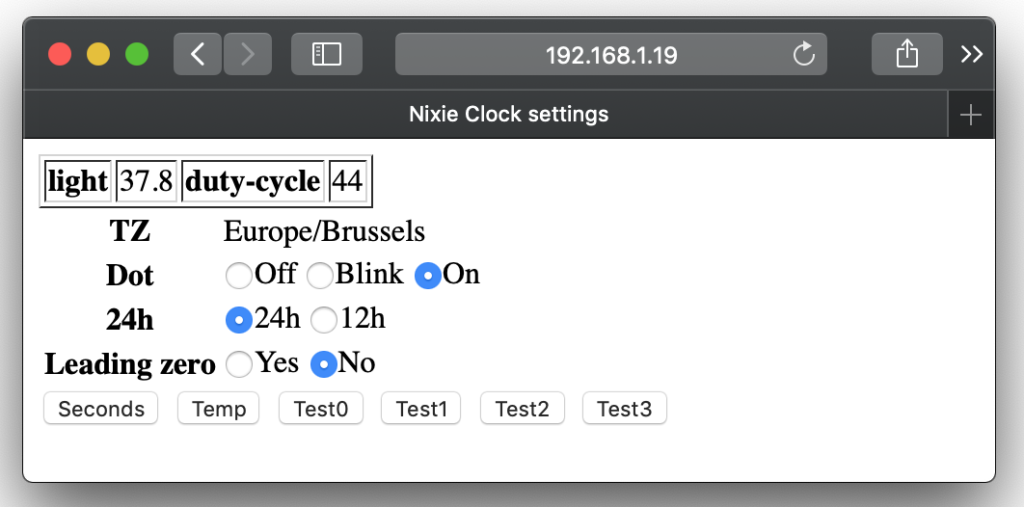
There are zero buttons on the case, none are needed to configure the clock – the Pi Zero W has WiFi and uses NTP to keep the clock accurate, while Linux handles daylight saving changes. During the last 3 seconds of each minute, the outside temperature is shown (obtained for a hardcoded locale through the OpenWeatherMap API). The Python code does run a webserver on port :8080 to allow some basic configuration (such as whether to show the leading zero or switch between AM/PM and 24h mode) and display some test patterns to help calibrate the duty cycle tables.
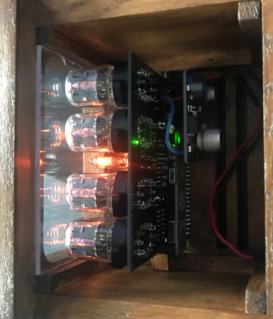
Finally, a friend CNC’d the panels for a wooden case that was painted in a suitably retro styling. A piece of plexiglass at the front shows off the Nixies and the PCB, and lets the light sensor see outside. The image below shows the construction, from left to right: the plexi glass window, Nixies mounted in sockets on the driver PCB, the Raspberry Pi mounted on the bottom using the 40-pin extension connector, and the high-voltage module.